
3 Amazing Halloween Arduino Projects for Teens
If your family is anything like mine, your teens are probably sick and tired of having yet another “vanilla” Halloween.
Scattering skeleton props all over your front yard. Or covering fake tombstones with fake (albeit super realistic) spiderwebs. Or putting candles into pumpkins. Or building a huge, 20-feet skeleton. Or similar “meh” effects that are plain, soulless, and frankly, boring.
So this year, I promised my three kids a one-of-a-kind Halloween, under a single condition – they have to create it by using an Arduino platform.
(If you’ve heard about Arduino in the past, but you’re not quite sure what it is, make sure to check our Arduino: LEGO for electronics guide.)
Using just ONE board, you can create:
- Screaming pumpkins or human skulls with scary LED lights.
- Skeleton heads that can talk and track your movements.
- Realistic big spider nests with RGB scary lights (the spider web project I made a couple of years back is nothing compared to this one).
- And bring back to life any spooky Halloween prop you have in your attic.
But why Arduino?
Why not connect some random lights, plug it into the socket, and shine like the guy next door?
You see, Arduino can help you breathe life into your Halloween and bring that spirit of being scary, yet cool to look at. Plus, the guys who invented the Arduino certainly had teens in mind, since they can’t get bored with it. Ever.
So what are the Halloween Arduino projects my three crafty t(w)eens are putting together to make our house the spooky center of attraction in the neighborhood?
Related Post: Arduino for Children: What It is and Why They Should Learn It
1. Motion Tracking Screaming Skull with Spooky Lights
Human skulls (plastic ones, of course) are scary to some people as is, but when you make them follow your movement, it gets even more spookier.
The main inspiration came from the Make Magazine’s Motion Tracking Skull project.
But hold on, did you think that was it?
Did I mention that we like to go super spooky with our Halloween celebrations?
That’s why we’re going to add some spooky lights into the skull’s eyes and a hidden speaker that will make it SCREAM every time somebody passes by.
The Spooky Components
So what kind of components would you need to make this new-level-of-Halloween-spooky project?
Here’s the list:
- Human skull (fake one, mind you!) – 1 pc
- Arduino UNO – 1 pc
- RGB LEDs (go with diffused ones, it will create a better effect) – 2 pc
- PIR Motion sensor – 1 pc. PRO TIP: there are multiple versions of motion sensors. Some track movement according to light (photosensors), while others track movement through super tiny sound waves. But when tracking movement during night, we found PIR sensors are best (they might even track zombies).
- Servo motor – 1 pc
- MP3 shield for Arduino (it uses an SD card, so you can upload and play various version of screams) – 1 pc
- 12V power supply – 1 pc
- Speaker – 1 pc. (We ended up using a pair of speakers we found from an old TV, since we actually made two moving skulls. Like making one wasn’t spooky and fun to make, right?)
- A bit of wire, resistors, solder, some hot glue, and soldering iron
Assembly Guide
If you’re a newcomer to the Arduino world, putting all those components together could be a bit overwhelming. And I know the feeling. I felt the same when I first started using this fun little thingy.
So that’s why we’ve found guides and how-to articles that will help you become more familiar with the RGB LEDS, motion sensors, servos, etc. Scroll down to the end of this article to find them! And I promise, after reading them, building any other super-spooky-cool Halloween project will be a child’s play for you.
Okay, now that you’ve gathered all of the components, what do you do with all of them?
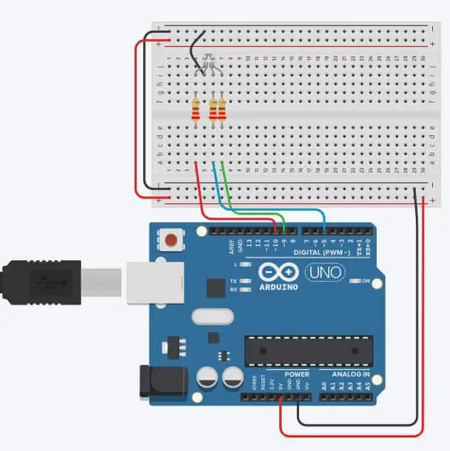
Let’s first start with putting together the RGB LEDs into the skull. But before you hot glue them, don’t forget to solder three resistors (220 ohms are good) to R, G, and B pins of the LEDs.
The connection should look like this:
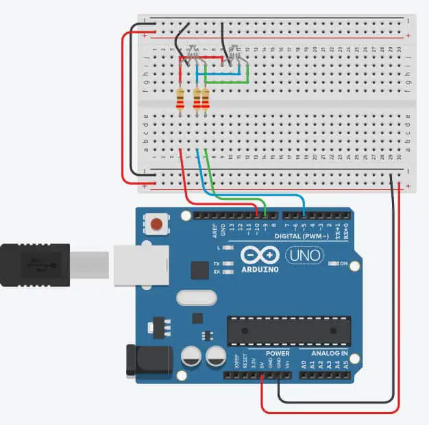
Now, since you’ll be using two LEDs, you can copy the connection and connect the second LED to the same resistors as the first one. Like this:
An amazingly useful tool for doing wiring, testing and coding all in one place is Tinkercad Circuits.
It’s super easy to use and learning Arduino programming is actually fun (my teens being programming hatters).
Also, there is a ready-made example of completely wired and programmed RGB LED that you can test. It will guide you through how the RGB LED works and what lines of code actually make different colors.
After you’ve done with connecting the RGB LEDs, it’s time to plant them into your spooky skull. In most of the skull props, the eye sockets already have a hole. So you can insert the LEDs into them.
The final result should look like this. Pretty spooky, right?
But remember: we want a skull that screams and activates the lights in its eye sockets when you pass by.
Time to download those good old-fashioned screams you’d find in horror movies. We’ve found that these female screams are what sends most chills down our spine.
***PRO TIP***
Make sure you download the MP3 version of the file, since that’s the format that your music shield accepts when programming the Arduino.
Oh, and don’t forget to assemble the music shield with the speaker (or speakers if you opt for the stereo effect of the scream) and the Arduino, as shown in the pic below.

***PRO TIP***
Connect the music shield first and RGB LEDs with everything else afterward. Trust us, we had to desolder and unwind the mess caused by a simple connection order.
Also, the left-over pins from the music shield are 10~, 9~,8, and 5~. So make sure you use the pins with ~ to connect your RGB LEDs, just like in the schematics diagram above.
What’s left is to attach one side of the servo motor to the skull and the second part to a piece of cardboard or plywood (plywood might be smarter since it won’t jump or flip when the skull is moving).

The last piece (PIR motion sensor) has to be hidden somewhere so that it wouldn’t be seen straight-away by the person.
If you’re putting this project outside, the ideal place for the PIR motion sensor is somewhere on the ground, tucked close to a pumpkin. But be careful not to fully hide the sensor so it isn’t able to detect movement.

So how should the servo and the motion be connected to the Arduino?
Simple! Like this (and here’s a secret – we’re going to HACK the rest of the pins on the Arduino).
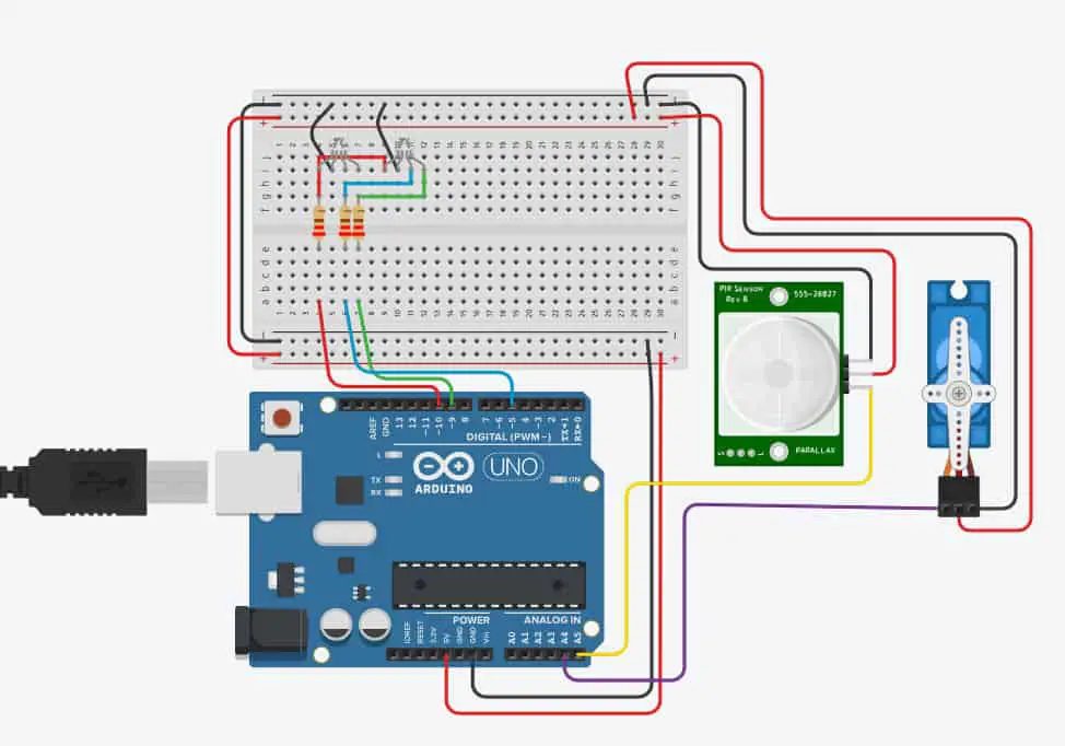
Seems pretty cool, right?
Oh, and don’t forget the music shield goes on top of the Arduino (the Tinkercad Circuits doesn’t have it included, that’s why it’s missing from the pic).
But simply connecting the components altogether wouldn’t be enough. We need to tell the big brains that’s placed inside that little chip on Arduino what to do and what songs to perform.
Here’s the secret code that will make you project the screaming attraction of this year’s Halloween:
#include <Servo.h>              //special servo library for controlling the servo

#include <SPI.h>                 //these are the libraries for the mMusic shield
#include <Adafruit_VS1053.h>
#include <SD.h>

#define CLK 13
#define MISO 12
#define MOSI 11
#define SHIELD_RESET  -1
#define SHIELD_CS     7
#define BREAKOUT_DCS    8
#define SHIELD_DCS    6
#define CARDCS 4
#define DREQ 3

Adafruit_VS1053_FilePlayer musicPlayer =
Adafruit_VS1053_FilePlayer(SHIELD_RESET, SHIELD_CS, SHIELD_DCS, DREQ, CARDCS);

Servo myservo;

int ledPin = 10;                // choose the pin for the LED pin 1
int ledPin2 = 9;                // choose the pin for the LED pin 2
int ledPin3 = 15;                // choose the pin for the LED pin 3
int inputPin = A5;               //the input pin (for PIR sensor)
int servoPin = A4;
int pirState = LOW;             // we start, assuming no motion detected
int val = 0;                    // variable for reading the pin status

void setup() {
  pinMode(ledPin, OUTPUT);      // declare LED pin as output
  pinMode(ledPin2, OUTPUT);      // declare LED2 pin as output
  pinMode(ledPin3, OUTPUT);      // declare LED3 pin as output

  pinMode(inputPin, INPUT);     // declare sensor as input

  myservo.attach(servoPin);     // connecting the virtual servo to to the physical servo pin

  Serial.begin(9600);

  if (! musicPlayer.begin()) { // initialise the music player
     Serial.println(F("Couldn't find VS1053, do you have the right pins defined?"));
     while (1);
  }
  Serial.println(F("VS1053 found"));

   if (!SD.begin(CARDCS)) {
    Serial.println(F("SD failed, or not present"));
    while (1);  // don't do anything more
  }

  // list files
 int printDirectory(SD.open("/"), 0);

  // Set volume for left, right channels. lower numbers == louder volume!
  musicPlayer.setVolume(20,20);

  // Timer interrupts are not suggested, better to use DREQ interrupt!
  //musicPlayer.useInterrupt(VS1053_FILEPLAYER_TIMER0_INT); // timer int

  // If DREQ is on an interrupt pin (on uno, #2 or #3) we can do background
  // audio playing
  musicPlayer.useInterrupt(VS1053_FILEPLAYER_PIN_INT);  // DREQ int

  // Play one file, don't return until complete
  Serial.println(F("Playing scream 001"));
  musicPlayer.playFullFile("/scream001.mp3");
}

void loop(){
  val = digitalRead(inputPin);  // read input value
  if (val == HIGH) {            // check if the input is HIGH
    analogWrite(ledPin, 204);   // tuns ON ledPin to create different colours
    analogWrite(ledPin2, 51);
    analogWrite(ledPin3, 204);
    myservo.write (60);         // the servo motor (skull) rotates 60 degrees

   if (musicPlayer.stopped()) {
    Serial.println("Done playing music");
    while (1) {
      delay(10);  // we're done! do nothing...
    }
  }
  if (Serial.available()) {
    char c = Serial.read();

    // if we get an 's' on the serial console, stop!
    if (c == 's') {
      musicPlayer.stopPlaying();
    }

    // if we get an 'p' on the serial console, pause/unpause!
    if (c == 'p') {
      if (! musicPlayer.paused()) {
        Serial.println("Paused");
        musicPlayer.pausePlaying(true);
      } else {
        Serial.println("Resumed");
        musicPlayer.pausePlaying(false);
      }
    }
  }

  delay(5000); // delay everything for 5 seconds
}
   else {
    digitalWrite(ledPin, LOW);
    digitalWrite(ledPin2, LOW);
    digitalWrite(ledPin3, LOW); // turns OFF all ledPIns
   myservo.write (0);    // the skull goes back into the initial position

  }
}
So you’ve read this far and you’ve set yourself and your teens to make this project?
Congrats! Let us know how your version of the project turned out. (I believe it’ll turn out EPIC!)
2. Bubbling Foggy Skeleton Head with Scary Lights
Again with the skeleton heads, right?
But trust me, this one is going to be a bit different.

How?
Besides creating a spooky Halloween project, you’ll also learn about the science part behind STEM. Understanding the science behind this project is what will give that cool out-of-the head bubbling effect.
But first, a word of caution.
This project includes working with dry ice! And the reason why it’s called dry is that it’s EXTREMELY cold (-108 F, yikes!)
And the fascinating thing about dry ice is – it’s not even a piece of regular ice as you would get from freezing water. It’s an actual solid form of CO2 (imagine solidifying a deadly gas?! #mindblown)
When you put just a tiny bit of dry ice in lukewarm water, it creates amazing bubbling foggy effects, like in the video below.
To give it a spookier look, we’re going to use RGB LEDs like from the previous project.
***PRO TIP***
When handling dry ice, always use gloves and NEVER take dry ice with your hands! Always use metal BBQ grippers.
The Spooky Components
Here are the components we’re gonna need for this Halloween project:
- Opened head skull – 1 pc
- Dry ice – around 5 lbs (try to find pellets of dry ice, they are way easier to work with)
- RGB LEDs – 2 pc (you can go with the same LEDs mentioned earlier)
- Arduino UNO – 1 pc
- 9 V battery – 1 pc
- Some solder, soldering iron, and hot glue gun
If you can’t find dry ice pellets, you can go DIY all the way and make dry ice at home.
It’s super easy and fun to do. Plus there’s nothing better than learning about science firsthand, in practice.
Just DO NOT touch it with your bare hands.
Assembly guide
Once you buy your open-head skull, you’ll have to make two holes at the bottom of it for the LEDs. And don’t forget to seal them with hot glue, as well as any other hole you can find.
Dry ice doesn’t like to be spilled.
Then, using a bit of solder and soldering iron, connect the LEDs to the Arduino UNO.
***PRO TIP***
To avoid the fuss with soldering, you can also use these kinds of breadboard cables (it’s a great connecting trick my teens discovered and saved a lot of time).
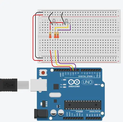
Here’s what the connection should look like:
What about the secret code that will control how our bubbling spooky skull would glow?
The code is actually simple. You can also make it glow with different kinds of colors after a period of time, making it an amazing Halloween attraction.
Here is what you’ll need to upload onto your Arduino.
// C++ code
//
void setup()
{
  pinMode(11, OUTPUT);
  pinMode(10, OUTPUT);
  pinMode(9, OUTPUT);
}

void loop()
{
  analogWrite(11, 204);
  analogWrite(10, 51);
  analogWrite(9, 204);
  delay(600000); // Wait for 600000 millisecond(s) - 10 min
  analogWrite(11, 51);
  analogWrite(10, 102);
  analogWrite(9, 255);
  delay(600000); // Wait for 600000 millisecond(s) - 10 min
  analogWrite(11, 51);
  analogWrite(10, 204);
  analogWrite(9, 0);
  delay(600000); // Wait for 600000 millisecond(s) - 10 min
}
The last step is to pour a bit of warm water into the skull, but not all the way to the top. Just enough for it to pass the middle.
Next, carefully add little pellets of dry ice, like in the Easy Cauldron Fog Effect video above. Please just don’t drop them, since spilled water and Arduino aren’t quite the best of friends.
Oh, and don’t forget to put a 9V battery to power everything up (it’s so embarrassing to admit, but we were trying to figure out why it wasn’t working the first time for an hour until we spotted there was a missing battery).
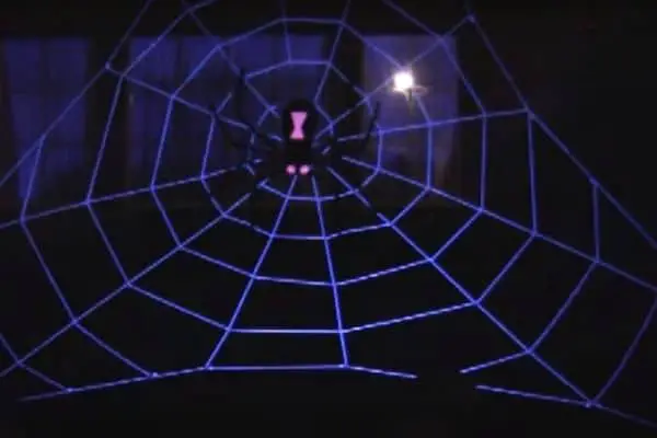
3. Glowing Unnerving Spider’s Nest
Imagine you’re walking down your driveway at night and suddenly a gasp-making-hair-raising spider’s nest lights up.
Pretty pulse-pounding, right?
But we like those unnerving Halloween projects, and in the steps below we’ll show you how we did it.
Ohh, and by the way, the web isn’t made out of ropes or anything like that.
Nooo, ropes are too boring and almost invisible at night.
We wanted the web to light up, jump-scaring you. So here’s a little secret thing we used instead of ropes – EL wires!
Wait, what? Wires?
Wires that also light up?
Yep, you read it right. And trust me, there is NO Halloween wizardry behind these.
EL wires are state-of-the-art lighting thingies that you can use to create all kinds of cool lighting effects without being constrained by the geometry of a shape you want to display.
Now, there are different styles of creating a spider’s web and nest, many of which you can choose from. But the ropes will be replaced with EL wires.
To make the whole web of EL wires suddenly light up, we need some kind of a module to turn it OFF and ON when we want it.
And there isn’t a better thing that will help us do that than a relay module.
But how do we control a relay?
Simple! Check out RandomNerdTutorials’s guide on relays that will help you get familiar with these handy little thingies.
The Spooky Components
Here are the components you’re going to need for this project:
- EL wires – around 10 meters (if you want to create a BIG spider’s nest)
- Relay module – 1 pc
- Arduino UNO – 1 pc
- 9v battery and a couple of regular 1.5V AA batteries
- A bit of solder, soldering iron, and a hot glue gun
The main purpose of a relay is to turn the whole web OFF and ON according to the code.
Assembly guide
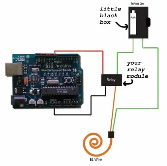
EL wires always come with their little black, magic (not black magic, that would be too spooky) box – their own power supply. It’s what gives them enough juice to shine so smoothly. Keep that little black box in mind because you’re going to modify it later on.
So, you’ve gathered all of the components and made your own spider’s nest of the EL wires?
Awesome job! You’ve done the toughest part.
But how do you connect Arduino, relay, and EL wires all together?
No-brainer! Take a look at our TinkerCAD’s schematic below.
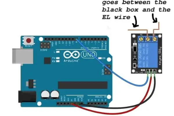
Or like this.
Okay, okay. This connection seems straightforward, but what about the code that will give the web that Halloween jump-scare effect?
Here it is:
void setup()
{
  pinMode(8, OUTPUT);
}

void loop()
{
  digitalWrite(8, 1);
  delay(600000); // Wait for 1 min
  digitalWrite(8, 0);
  delay(30000); // Wait for 30 sec
}
Plain and simple, right?
***PRO TIP***
Don’t forget to attach the 9V battery and to put the whole Arduino thingies into a zip bag. If it rains in your areas for Halloween, the zip bag will prevent your Arduino from getting short-circuited and starting to smoke.
Summary
These are the Arduino projects my three teens (with some help from yours truly) are making for this Halloween.
It’s also something I believe will give your teens an amazing experience and make your house a center place of this year’s Halloween spookiness.
Further reading & how-to articles:
- How to work with RGB LEDs
- How to work with PIR motion sensors
- How to work with music shields for Arduino
- How to work with servo motors